


ABSORPTION/ABSORBER
In absorption, a vapor solute A in a gas mixture (inert gas+ solute A) is absorbed by means of a liquid in which the solute is more or less soluble. The liquid is primarily immiscible in the gas phase; its vaporization into the gas phase is small/negligible. Ex: Absorption of the ammonia(A) from an air-ammonia mixture by water. The reverse process is desorption or stripping.

There are 2 types of tray as below
TRAY TYPE:
Types of tray (plate) towers for absorption:
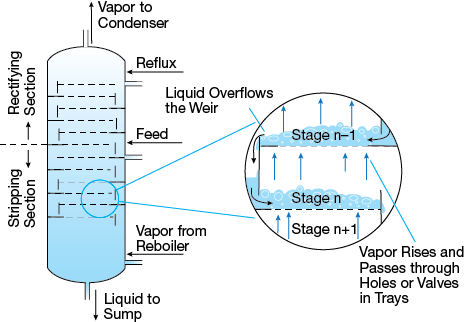
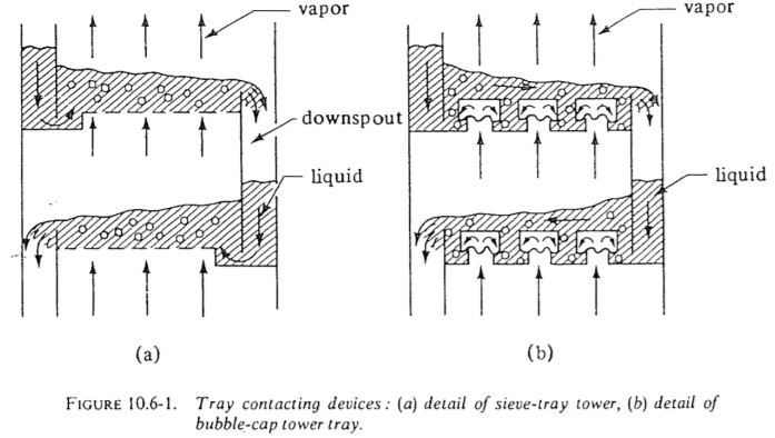
Sieve tray: Vapor bubbles up through simple holes in the tray through the flowing liquid. Hole sizes range from 3 to 12 mm in diameter, with 5 mm a common size. The vapor area of the holes varies between 5 to 15% of the tray area. The liquid is maintained on the tray surface and prevented from flowing down through the holes by the kinetic energy of the gas or vapor. The depth of liquid on the tray is maintained by an overflow, outlet weir. The overflow liquid flows into the downspout to the next tray below.
 Valve tray: A modification of the sieve tray is the valve tray, which consists of openings in the tray and a lift-valve cover for each opening, providing a variable open area which is varied by the vapor flow inhibiting leakage of liquid down the opening at low vapor rates. Hence, this type of tray can operate at a greater range of flow rates than the sieve tray, with a cost of only about 20% higher than a sieve tray. The valve tray is being increasingly used today
Bubble-cap tray: The vapor or gas rises through the opening in the tray into the bubble caps. Then the gas flows through slots in the periphery of each cap and bubbles upward through the flowing liquid. Bubblecap trays are expensive
PACKED TYPE
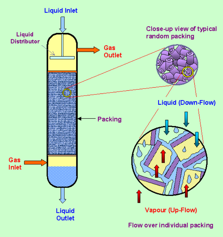
These are used for continuous countercurrent contacting of gas and liquid in absorption and also for vapor-liquid contacting in distillation. The tower in the consists of a cylindrical column containing a gas inlet and distributing space at the bottom, a liquid inlet and distributing device at the top, a gas outlet at the top, a liquid outlet at the bottom, and a packing or filling in the tower. The entering gas enters the distributing space below the packed section and rises upward through the openings or interstices in the packing and contacts the descending liquid flowing through the same openings. A large area of intimate contact between the liquid and gas is provided by the packing
Common types of which are dumped at random in the tower are shown in Fig. 10.6-3. Such packings and other commercial packings are available in sizes of 3 mm to about 75 mm. Most of the tower packings are made of inert and cheap materials such as clay, porcelain, graphite, or plastic. High void spaces of 60 to 90% are characteristic of good packings. The packings permit relatively large volumes of liquid to pass counter currently to the gas flow through the openings with relatively low pressure drops for the gas. These same types of packing are also used in vapor-liquid separation processes of distillation. Stacked packing having sizes of 75 mm or so and larger is also used. The packing is stacked vertically, with open channels running uninterruptedly through the bed. The advantage of the lower pressure drop of the gas is offset in part by the poorer gas-liquid contact in stacked packings. Typical stacked packings are wood grids, drip-point grids, spiral partition rings, and others.
In a given packed tower with a given type and size of packing and with a definite flow of liquid, there is an upper limit to the rate of gas flow, called the flooding velocity. Above this gas velocity the tower cannot operate. At low gas velocities the liquid flows downward through the packing essentially uninfluenced by the upward gas flow. As the gas flow rate is increased at low gas velocities, the pressure drop is proportional to the flow rate to the 1.8 power. At a gas flow rate, called the loading point, the gas starts to hinder the liquid downflow and local accumulations or pools of liquid start to appear in the packing. The pressure drop of the gas starts to rise at a faster rate. As the gas flow rate is increased, the liquid holdup or accumulation increases. At the flooding point, the liquid can no longer flow down through the packing and is blown out with the gas. In an actual operating tower, the gas velocity is well below flooding. The optimum economic gas velocity is about one half or so of the flooding velocity. It depends upon an economic balance between the cost of power and the fixed charges on the equipment cost.